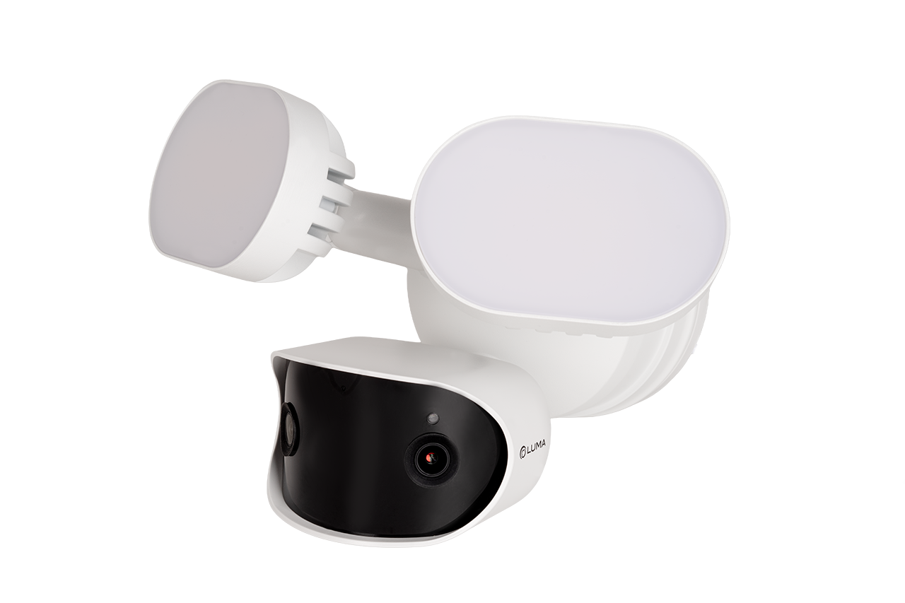
720-IP-FLD contents

  • camera

  • mounting template

  • 4 × wall anchors with screws

  • weatherproofing kit

  • center screw

  • support strap

PoE advisory

Caution: This camera requires 60W of PoE to function. We recommend using the Luma x20 Gigabit 60W PoE injector.

Click here to download a PoE calculator in MS Excel.

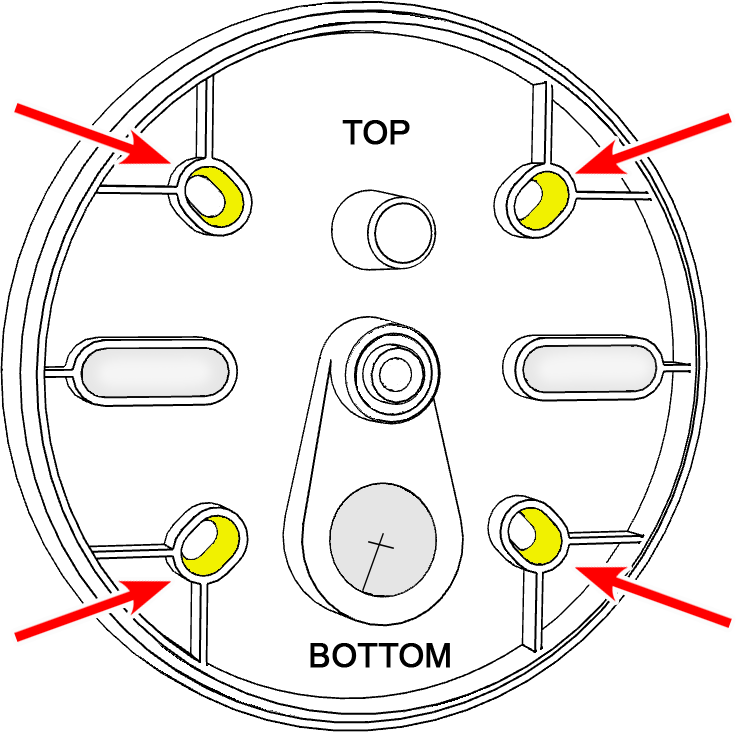
Review mounting plate orientation

Rotate the mounting plate until the round post is ABOVE the center screw, and the large hole for cable routing is BELOW the center screw.

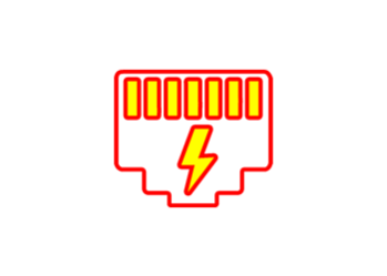
Locate cable management features

Identify the recessed area on the camera body for excess cable, and the cable routing hole on the mounting plate.

Confirm the round post is above the center screw and the cable-routing hole is below the center screw.

Prepare the surface

Using the mounting plate as a guide, drill pilot holes in the desired location.

Note: Rotate the mounting plate until the round post is ABOVE the center screw, and the largest hole for cable routing is BELOW the center screw.

Attach the mounting plate

Screw the mounting plate to the wall/surface.
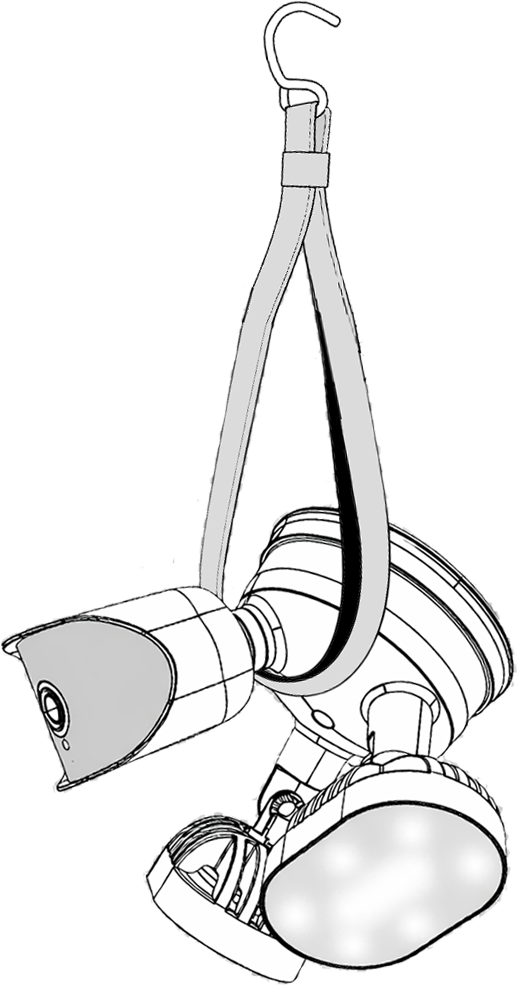
Support the camera

Hang the camera by the included strap.

Weatherproofing: Prepare the tail

Find the white washer in the weatherproofing kit.

Place it on the network connector of the camera's tail. The proper placement is shown here in yellow.

Weatherproofing: Insert the network cable

Slide a terminated category cable through the end cap and the casing.

Weatherproofing: Connect the tail

Connect the terminated cable to the network connector of your camera's tail.

Weatherproofing: Secure the casing

Slide the weatherproof casing firmly onto the camera's network connector. Twist it to lock it in place.

Weatherproofing: Insert the sealing gasket

The sealing gasket has a slit in the side. Use this slit to place the gasket around the cable, then slide the gasket fully into the weatherproof casing.

Weatherproofing: Attach the end cap

Screw the end cap onto the casing until it is snug. The compresses the gasket around the cable, providing a weatherproof seal.

Open the utility port to add an SD card or access the reset button (optional)

On the bottom of your camera, loosen the screws that cover the utility port. Remove the cover.

Add an SD card (optional)

You can insert an SD card (up to 256GB) into the card slot in the utility port, shown here. Use only a surveillance-rated SD card.

Reset button (optional)

This button (shown in yellow) is the reset button.

If needed, while the camera is powered, press and hold this button for 30 seconds to restore it to factory defaults.

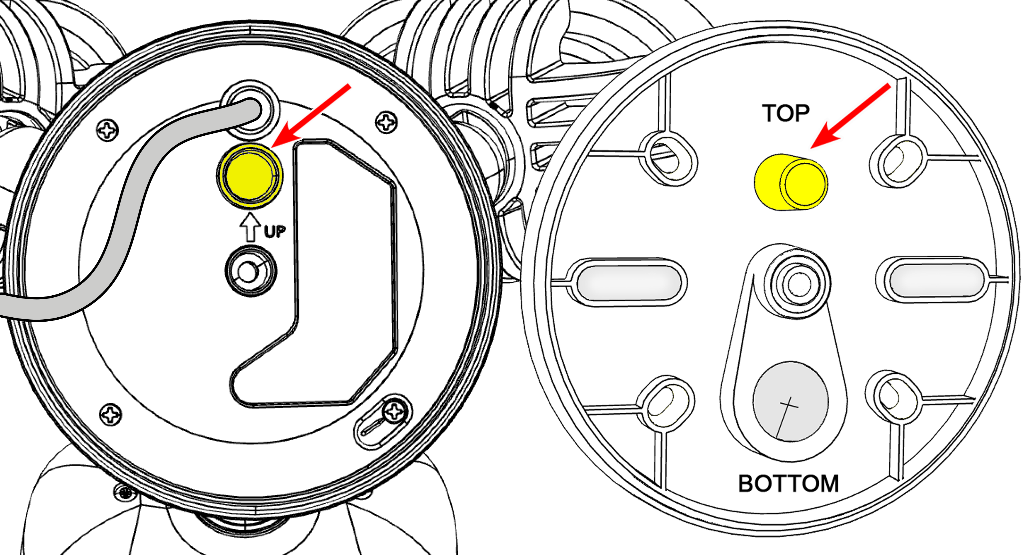
Route the cable through the mounting plate

Note: Confirm the round post is above the center screw and the cable-routing hole is below the center screw.

Gently secure excess cable in the recessed area on the camera body to prevent crimping, then route the pigtail through the mounting plate.
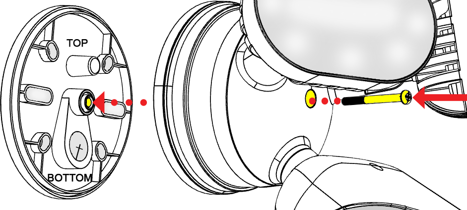
Mount the camera

Insert the long center screw through the camera body and the mounting plate.
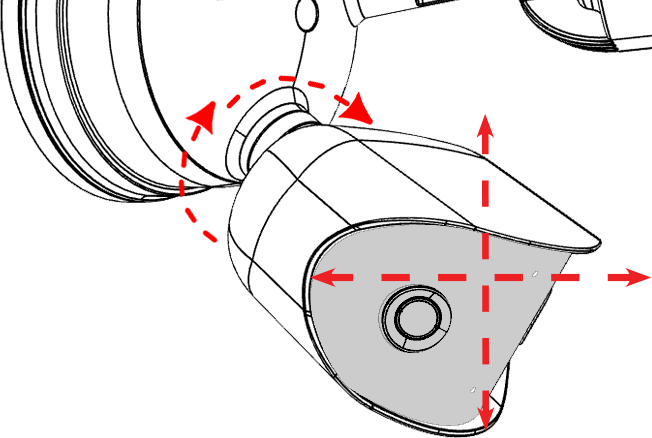
Aim the camera

Tilt or rotate the camera as needed.
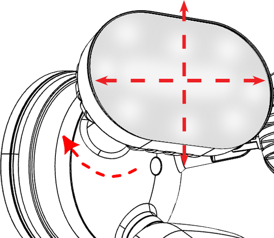
Aim the floodlights

Tilt or rotate each flood light as needed.

Claim the camera in OvrC

If you have an OvrC Pro device, it automatically claims your camera. If not, claim it by manually entering its MAC address and service tag number. Once claimed, activate the camera in OvrC to help you adjust its aim.